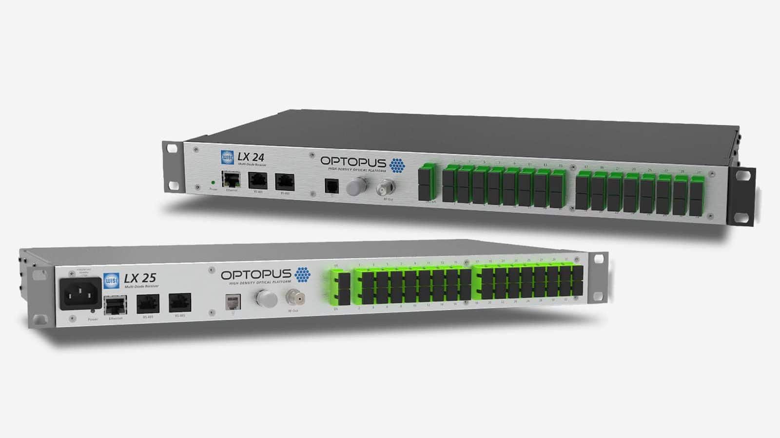
RFoG Upstream Receiver
RFoG Deployments Made Easy
- Works with existing RFoG infrastructure
- Electrical/optical upstream, single/dual fiber, CWDM wavelengths US Tx
- SC/APC or LC/APC
- Port density of 32/16/8 fiber node ports
- Optional EDFA (downstream)
- Fixed front connector or pluggable LXPS
- Enable/Disable subscriber lines remotely
- Upstream power monitoring per port
RFoG Upstream Receiver LX 24/LX 25
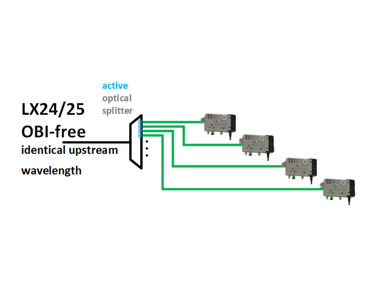
Upgrading your network infrastructures to OBI-free (Optical Beat Interference) RFoG networks with this active upstream receiver. Use up to 32 output ports (or cascade them to reach higher port numbers) and eliminate issues instantly with the dedicated upstream receivers. Each of these ports provides an input power measurement in real time and can be shut off if necessary (testing purposes or subscriber service shutdown). That’s why the LX 24/LX 25 enables network providers to heal existing OBI-infected RFoG networks without any need to swap existing end user equipment. The solution will work with any upstream wavelength and laser mode. OPTOPUS and its OBI-free RFoG technology offer network providers a complete future-proof concept, while opening the doors for new FTTx deployments.

OBI Features
When two optical transmitters of the same or similar wavelengths are received on the same upstream port, Optical Beat Interference occurs.
Being a purely statistical issue, OBI will occur due to the temperature-based wavelength drift and the manufacturing consistency of each laser.
The noise floor drastically increases and the C/N is destroyed.
If two optical transmitters utilize different wavelengths on the same upstream port, Optical Beat Interference won’t occur.
The problem hereby is more an operational one. All types of fiber nodes (wavelength) need to be present at the installer site instead of the standard 1610 nm node only.
Optical Beat Interference is completely eliminated when the upstream signals are actively combined (dedicated receiver diode per port with following electrical combining).
This keeps the necessary noise floor and provides sufficient signal performance along the upstream path.
Cascading active splitters (MDRs) is possible due to the electrical conversion and combining of the received optical upstream signals before transmitting them into the second upstream receiver in the next higher hierarchy level of the architecture.